ASTM D5453
Standard Test Method for Determination of Total Sulfur in Light Hydrocarbons, Spark Ignition Engine Fuel, Diesel Engine Fuel, and Engine Oil by Ultraviolet Fluorescence
ASTM D5453 is one of the most used standard test method for the determination of total sulfur content in liquid hydrocarbon matrixes boiling in the range of 25 to 400 °C. Viscosities for this method lay between 0.2 and 20 cst(mm2/S). Samples like naphthas, diesel, jet fuels, kerosenes, engine oils, ethanol, Fatty Acid Methyl Esthers(FAME) and their blends with fossil diesel, gasolines oxygen enriched and ethanol and methanol blends such as E85, M85 and RFG can be analyzed by this method utilizing direct syringe injection. Precision statement was calculated based on samples containing total elemental sulfur between 1 and 8000 mg/kg.
D5453 is the preferred method for the quantitative determination of trace sulfur in a wide variety of hydrocarbon samples. This is due to a series of instrumental advantages among which is worth mentioning: linear dynamic ranges of better than 10:3; excellent stability of the system that provides for high precision analysis; conversion of all sulfur species into a common analyte (SO2) eliminating matriz effects; quantitative and fast water stripping step to reduce the most important quenching source; unsurpassed signal to noise ratios, major contributor to the very low limits of detection achievable by this technique. The UV-Fluorescence technique is equimolar and the response of the detector is linear in a broad concentration range which signifies that any organic S containing compound can serve as a calibration standard and the calibration curve can be built with a minimum of calibration points. “TSHR model TS7000 analyzer possesses all instrumental properties to guarantee fast, reliable and accurate experimental results. Based on these characteristics the system meets with great ease the precision and accuracy criteria of EPA 40 CFR Part D Sub-part 80 Section 80.47 protocol qualifying it to report S contents in Tier III gasolines, LPG for gasoline blending and ultra-low sulfur diesel samples”. (Aaron Mendez Ph.D.)
Method Summary:
A measured quantity of the hydrocarbon sample is either directly injected into the pyrotube of the analyzer at a controlled speed into the vaporization and combustion zones of the instrument. In the inlet zone the sample is transported by an inert stream of a carrier gas, typically Argon or Helium. The hydrocarbon is oxidized in a rich pure oxygen stream in the combustion zone at approximately 1000°C where it is converted into CO2, SO2 and H2O. After the gases exit the combustion zone they are passed through a semipermeable Nafion® membrane where the water is quantitatively removed. The gases enter the Sulfur reaction chamber where they are exposed to an UV light. The SO2 molecules absorb the radiation and become excited. The relaxation takes a few nanoseconds releasing a secondary energy which is captured by a Photo Multiplier Tube, amplified processed and recorded. The signal obtained is proportional to the total sulfur content of the original sample.
Apparatus
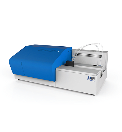
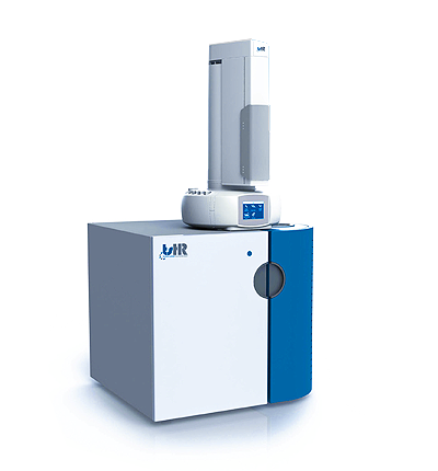
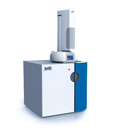
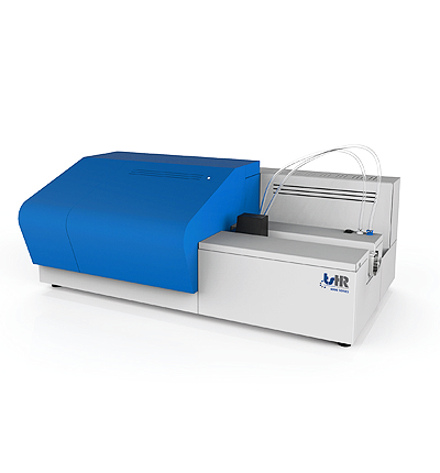
The analyzer of vertical configuration for volatile organic compounds is represented in fig.1. The system is provided with an automatic sample changer and a vaporization inlet system 1; a dual zone combustion furnace 2; the membrane dryer 3; a precautionary particle filter 4; the UV source 5; the PMT detector 6 and the signal acquisition and processing unit 7. 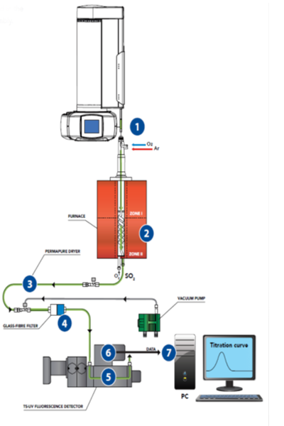 Diagram Some manufacturers like the one displayed above have modified the inlet system to be able to consistently inject liquid samples with higher viscosities. For viscous and solids samples there are horizontal configuration systems where a weighed sample amount is place in a boat inlet system and driven into the combustion tube by a motor driven mechanism at a controlled speed. A horizontal configuration system is shown in Figure 2. Typically, these systems also have a liquid’s module where syringable liquid samples can also be injected into the pyrotube in a similar fashion as in the vertical instrument.
Test Procedure:
Apparatus preparation and calibration: Once the system has been assembled, leak tested, heated and stabilized per the instrument manufacturer, typical operating conditions like Table 1 of D5453 are stablished and adjusted as per the manufacturer’s guidelines. Based on anticipated sulfur concentrations needs the instrument is then calibrated either by dilution of a stock solution or using a calibration kit from commercial standard reference laboratories. Set the calibration method to average three consecutive injections for each calibration point. Check the linear regression coefficient of the obtained calibration curve and make the necessary corrections should the linearity not be in accordance with ASTM D5453 and the manufacturer’s instructions ( R2 ≥ 0.999 or 1 to 2 orders of magnitude for the calibration range). It is a good laboratory practice to start the calibration in ascending order to reduce risk of carryover that could affect the linearity of the calibration. Analysis: Prepare a sequence of analysis for the samples to be analyzed under the same unaltered experimental conditions and again taking the average of three consecutive injections. Sulfur concentrations of the unknown samples should fall in the calibration range. Perform dilutions on gravimetric or volumetric basis if necessary. Measure the response of the system for the test solution and inspect the combustion tube and the flow tubing of the instrument after the sample analysis to verify complete combustion. Soot should not be detected. In case the soot formation is detected care should be taking by reducing sample size or rate of injection after cleaning the systems as per manufacturer’s instructions. Densities needed for the calculations are to be measured by ASTM Test Methods D1298 and D4052 at the test temperature. Experimental values and QC/QA control samples should fall within the precision estimates of table 1 below.
| Concentration (mg/kg S) | r | R |
|---|---|---|
| 1 | .2 | .6 |
| 5 | .6 | 1.9 |
| 10 | 1.0 | 3.3 |
| 50 | 3.4 | 10.9 |
| 100 | 5.7 | 18.3 |
| 400 | 16.0 | 51.9 |
Table 1. D5453 Repeatability and Reproducibility valuesThe interlaboratory studies to determine the precision of D5453 was divided as follows: Repeatability “r” _ Differences of two consecutive test results with the same apparatus, run by the same operator on the same sample should exceed by more than one case in twenty: Less than 400 mg/kg S r = 0.1788 X (0.75) Greater than 400 mg/kg S r = 0.02902 X X _ Average of two experimental results Reproducibility “R” _ Difference between two single experimental results on the same sample at identical conditions performed in different instruments by different operators should not exceed the value for more than one case in twenty Less than 400 mg/kg S R = 0.5797 X (0.75) Greater than 400 mg/kg S R = 0.1267 X X _ Average of two experimental results Bias _ No significant bias was determined in the ILS (RR:D02-1547 2001), except for the NIST SRM 2298 (4.6mk/kg) and 2299 (13.6 mg/kg), that showed -0.97 and -2.00 respectively. Experimental parameters such as sample sizes; flows, and temperatures should be used in accordance with the manufacturer’s operation manual. The same applies to experimental procedures to keep the system in optimum conditions and free of contamination. For TIER III gasolines the Performance Based Measurement System is critical and to report D5453 the system must qualify prior to the analysis. The qualification is based on achieving the 40 CFR 80 D 80.47 precision requirement. This requirement will not be possible if the instrument is not stable enough as to produce a low data dispersion. So the complete combustion of the sample, the selection of the optimum UV wavelength, the low noise and stable base line as well as the effective water removal process are critical points to be observed and met to successfully comply with the new EPA requirements.
We offer the following Instruments that cover this method:


